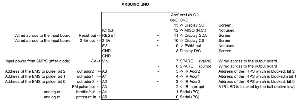
- ARDUINO UNO PINOUT BLACK AND WHITE SERIAL
- ARDUINO UNO PINOUT BLACK AND WHITE SOFTWARE
- ARDUINO UNO PINOUT BLACK AND WHITE CODE
You can learn Arduino programming from the internet/youtube as there are a ton of quality material available there.
ARDUINO UNO PINOUT BLACK AND WHITE SERIAL
Any other serial command will not work if this is not used in void setup().Īnd I understand that learning Arduino can be very difficult if you are an absolute beginner. Serial.begin(9600) command initialize the communication hence goes into the void setup(). In your case, you can use the Serial monitor to print the real-time sensor readings(0 or 1) for sensor calibration and better control. You can also send data to the Arduino board using this serial monitor(using appropriate serial commands).

The data gets printed onto the Serial monitor of the Arduino software.
ARDUINO UNO PINOUT BLACK AND WHITE SOFTWARE
Serial commands are used for serial communication between the Arduino board and Arduino software to receive data(such as from the sensor, keyboard)/send data. You can use serial commands for real-time sensor data collection. I haven’t tested it on the actual setup but this should work.Ĭontrolling 5 different LEDs from 5 different IR Sensors:Ĭonst int IR1 = 2, IR2 = 3, IR3 = 4, IR4 = 5, IR5 = 6 // IR sensors connected from digital pin 2 to 6Ĭonst int LED1 = 9, LED2 = 10, LED3 = 11, LED4 = 12, LED5 = 13 // LEDs connected from digital pin 9 to 13įor (int i = LED1 i <= LED5 i++) // LED's connected from pin 9 to 13įor (int i = LED1 i <= LED5 i++) // Initially all LED's are kept OFF
ARDUINO UNO PINOUT BLACK AND WHITE CODE
I have compiled this code for you as fast as I could. Now depending upon the number of Pins and potentiometer you may come across different versions of Ir Sensor. Before we get to uploading code and sending data to the display, let’s hook the display up to the Arduino. Wiring OLED display module to Arduino Uno. SDA is a serial data pin for I2C interface. SCL is a serial clock pin for I2C interface. There are generally two LEDs on the IR sensor, one is a power indicator and the other one is the output/obstacle indicator. VCC is the power supply for the display which we connect the 5 volts pin on the Arduino. So by rotating the potentiometer you can set the detection distance. The single potentiometer on most of the IR sensors is used to set the sensitivity of the sensor or the distance up to which it detects the obstacle. IR receiver constantly sends digital data in the form of 0 or 1 to the Vout pin of the sensor. Whereas the work of the IR receiver is to receive these transmitted infrared waves. The work of an IR transmitter or Infrared transmitter is to transmit the infrared waves. Board layout of an IR SensorĮvery IR Sensor or Infrared Sensor has two main parts.

For example, a TV remote uses light waves just beyond the visible spectrum of light-infrared light waves-to change channels on your TV.Īnd Ir sensor uses the same waves to detect the obstacle. You may not be aware that you encounter Infrared waves every day. But unlike sunlight/visible light, the human eye cannot see IR waves. Just like visible light, Infrared wave/light is part of the electromagnetic spectrum.


 0 kommentar(er)
